Welcome to ILITCH ELECTRONICS BLOG page
On this page we post a series of installation tips for our hum canceling systems. Also we will discuss some basic principles and knowledge base for you to better understand how the electric guitar works and how the electromagnetic pickups create an output electrical signal
An example about how to measure guitar control cavity circumference fit and size:
All of our CVNCS IN designs will require you to measure the guitar control cavity size and estimate its shape fit. In that way you will know, the product will fit and the installation is going to be easy and successful.
All you need to do is to use a flexible tailor measuring type or piece of heavy gauge wire or a long enough strip made of paper.
Place the measuring tool next to the inside of the cavity outline wall. Then somehow mark start and end points
Later – take the measuring tool out and measure its length in millimeters or inches.
Based on the number you get – you select the product that is best fit.

Preparing your Tele pickups for installation of PGNCS T hum canceling system
Tele Bridge pickup output wires modification:
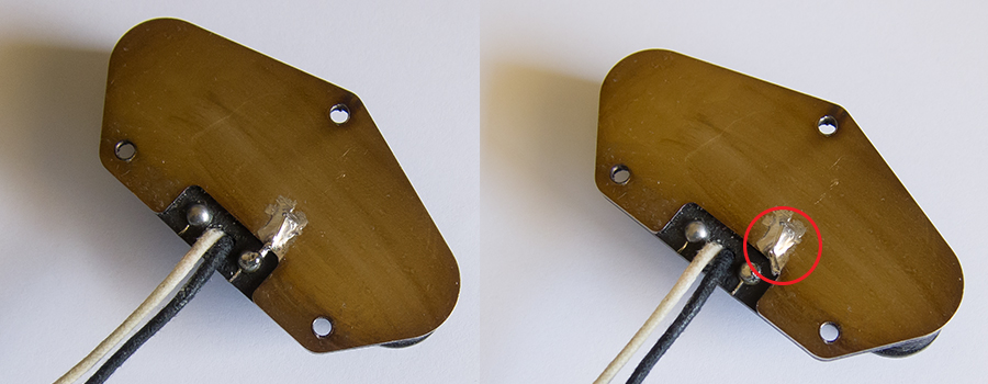
Most Tele bridge pickups come with a metal base plate. The base plate is attached to the bottom of the pickup and it is connected to the pickup black wire using a short bare wire jumper. In this way, the base plate is grounded. When installing the Ilitch hum canceling system, the black ground wire of the Bridge pickup must be separated from the guitar GROUND.


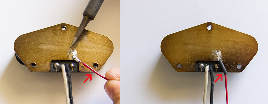
In order to keep the base plate securely grounded, you need to run an additional wire from the base plate ONLY to the control cavity. On the picture this is the red wire (could be any color flexible wire) and it needs to be connected to the Volume potentiometer housing. The Black Bridge pickup wire is now available to be connected to the Blue wire from the Adjusting PCB. This modification converts the Bridge pickup from 2-conductor to 3 conductor output wire, and makes it ready to be connected to the system.
Note:
Some Tele guitars originally use the same black wire of the bridge pickup to ground the guitar bridge plate. When we modify the bridge pickup output wires, it is better to run a separate wire to ground the bridge plate because it cannot be securely grounded via the 3 bridge pickup mounting screws. This separate wire will need to be soldered to the main guitar ground on the volume pot housing.
Tele Neck pickup output wires modification:
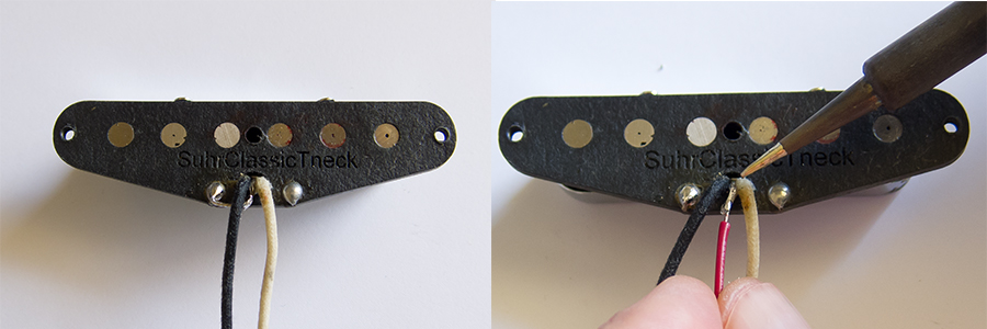
Most Tele neck pickups come with a metal cover which covers and shields the neck pickup. The cover is connected to the pickup black wire using a short bare wire jumper. When installing the Ilitch hum canceling system, the ground connection of the Neck pickup must be separated from the guitar GROUND. In order to keep the neck cover grounded, we recommend running additional wire from the neck cover to the control cavity.
On the picture this is the red wire (could be any color flexible wire) and it needs to be connected to the Volume potentiometer housing. The Black Neck pickup wire is now available to be connected to the White wire from the Adjusting PCB. This modification converts the Neck pickup from 2-conductor to 3 conductor output wire, and makes it ready to be connected to the system

More tips and knowledge base coming soon